Introduction
Overview of the improved J-tube system
The improved J-tube system has been developed for offshore wind turbine foundations, particularly monopile type foundations. The improved J-tube system is a newly Patented system that is available for use on all future projects.
The improved J-tube system has been specially developed to allow monopile foundations to be constructed in the most economical way possible. The improved J-tube system utilises external J-tubes and does not require any attachments to the monopile or J-tube holes through the monopile. Furthermore, the improved J-tube system is also quick and simple to install.
The improved J-tube system comprises a sliding J-tube assembly and an embedment into the seabed. The J-tube can be installed to any level required and then remotely secured into position. The improved J-tube system does not rely on the use of divers and does not require the use of bespoke or additional heavy equipment or vessels.
Advantages
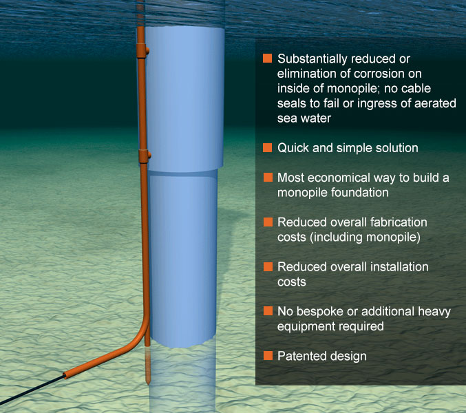
A summary of the advantages of the improved J-tube system
- The improved J-tube system allows the fabrication costs of both the primary and secondary steelwork to be kept to a minimum. This is because the improved J-tube system requires no attachments or fixings to the monopile, or J-tube holes through the monopile. As the design of the primary steelwork, in particular the monopile, is generally governed by fatigue requirements this means the monopile can be fully optimised for minimum plate thickness and minimum weight, etc. The only welded attachments required to the main structure tend to be higher up the structure in regions of lower stress, e.g. within the grouted joint of the transition piece. Being able to fully optimise the monopile in this way can provide a significant weight saving of the prmary steelwork and therefore significantly reduced overall fabrication costs.
- The improved J-tube system also allows the overall installation costs of the foundations to be kept to a minimum. This is due to the improved J-tube system being quick, simple and reliable to install, but also because the main structure can be optimised to be as light as possible. Only two operations are required for installation; firstly the J-tube assembly is pushed into the seabed and then secondly the top supports are remotely secured. In this way the overall installation time on site can be kept to a minimum, and as time on site is a major cost consideration for offshore structures, this is a significant cost advantage.
- The J-tubes can be lowered into position and installed to any level required. This is easier for transportation and particular useful where the seabed levels and/or installation levels of the main structure vary. Large installation tolerances can be accommodated if necessary, i.e. monopiles can be overdriven or underdriven if required. This means it may also be possible to reduce the average embedment depth of the monopiles across a site, and/or provide a more flexible approach when the geotechnical information is limited.
- The installation does not require the use of bespoke or additional heavy equipment or vessels. In addition, little development costs are required. All operations utilise well established technologies, e.g. conventional pile installation and grouting.
- Scour holes can be accommodated (either already present or future). As J-tubes are designed as simply-supported or fixed-end beams these can be designed to span any potential scour holes as required.
- The use of divers is not required. The top supports of J-tube can be secured remotely underwater. This is a significant saving in its own right as the use of divers can add considerably to costs and delays, in addition to the safety issues.
- Cable pulling forces can be resisted directly. J-tubes are designed as beams supported each end and are therefore much stronger than those designed as cantilevers.
- The system is reliable and relatively risk-free in terms of potential for things to go wrong or delays on site. In addition, the installation is relatively non-weather dependent.
Features
Features of the improved J-tube system
- The improved J-tube system can be installed to any level as prior to installation the whole assembly is able to slide up-and-down. The improved J-tube system has no attachments to the monopile, instead support to the bottom of the J-tube is provided by having an embedment into the seabed. In addition, the top supports of the J-tube can be remotely secured by the use of grouting.
- It is anticipated that with monopile foundations the top supports of the J-tube assembly will be fabricated as part of the transition piece. Prior to installation the J-tube assembly is held as high as possible on the transition piece in order to ease storage and facilitate transportation, etc.
- The J-tube assembly is composed of the usual vertical pipe with a 90° curve at the bottom, but has the added feature of another vertical tube or spike extending below the heel of the J-tube proper. Once the transition piece has been installed, the J-tube assembly complete with lower section can be lowered to the seabed. The J-tube is then driven, vibrated, or pushed into the seabed. Application of the necessary forces to vibrate or push the lower section is applied at the top of the J-tube assembly using readily available conventional piling equipment.
- Vertical installation of the J-tube assembly ceases when the toe of the lower section reaches the desired embedment depth and/or the height of the curved section reaches the desired level for cable entry, etc. Scour holes can be accommodated (either already present at time of installation or those that may develop in the future) by simply making the lower section longer than otherwise would be required.
- The top support or supports of the J-tube can be secured remotely by the use of grouting. This is readily achieved by the use of concentric tubes, i.e. the vertical section of the J-tube assembly slides up-and-down within another tube forming the top support or supports. Once the J-tube is installed into the seabed the gap between the outside of the J-tube and inside of the top supports is filled with grout. The volume of grout is likely to be small (e.g. 25mm to 50mm gap) and the required grout strength need only be of medium to high strength. Grout seals are required at the ends of the top supports and these, together with the grout pipes, can be preinstalled on the transition piece prior to transportation to site.
- The advantage of grouting in this way is that the top supports can be secured quickly and simply and without the use of divers. As the top supports are secured remotely, the lowest top support can be as low down on the transition piece as is possible, i.e. to reduce the span and therefore size of the J-tube to a minimum. Alternatively the top supports can be made by conventional mechanical means and/or the top supports designed as permanently sliding supports.